
Inverter controller
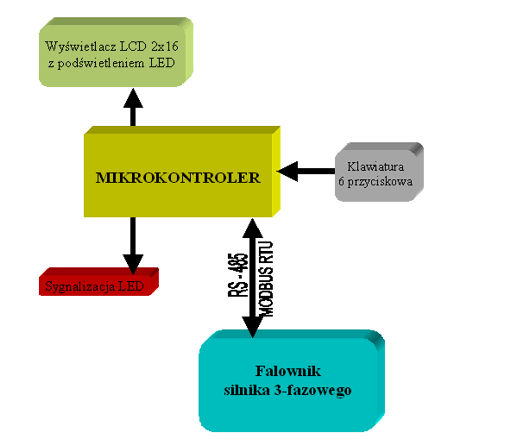
Block diagram of the inverter controller
Technical parameters of the inverter controller:
- 2×16 character LCD display, with LED backlight;
- 6-button keyboard;
- 4 LEDs indicating the operating status;
- RS-485 interface, used to communicate with the inverter using the MODBUS RTU protocol;
The inverter controller was designed to control the cyclic operation of the inverter which was connected to a 3-phase motor. Parameter settings are made from the keyboard and are displayed on a 2×16 character LCD display. The controller communicates with the inverter via a serial RS-485 connection, MODBUS RTU protocol. The operating status is indicated by LEDs.
The controller enables the engine to operate according to the following parameters:
- engine speed;
- turning direction;
- turn on, turn off the engine;
- engine operating time at a specific speed.