
Programmable universal controller SU 1.2


1. Driver description
The freely programmable Universal Controller SU 1.2, thanks to its compact structure, high efficiency and the ability to process programs and processes in real time, is dedicated to manufacturers of machines and devices. It is intended for use in industrial automation systems.
Characteristic features of the SU 1.2 driver:
8 digital inputs, including 2 fast inputs (e.g. reading of fan tacho generator signals),
8 logic outputs,
2 analog inputs (voltage 0..10V),
2 analog inputs (temperature – PT100 sensor),
2 analog outputs 0..10V,
RS232/485 communication port,
LCD display,
programmable 6-button keyboard,
real time clock (RTC),
acoustic signaling device (buzzer),
signaling the states of digital inputs and logical outputs,
mounting on a DIN TS35 rail,
24V DC and 24V AC power supply.SU 1.2 Universal Driver Specification.
Thanks to the integrated serial interface, RS 232/485, the SU 1.2 controller can be connected to an existing control system in an industrial network, e.g. Profibus, DeviceNet, Ethernet, etc. In this way, using appropriate converters, the SU 1.2 controller can be connected to a working already a system based on PLC controllers.
The RS485 interface also allows you to build a new system by connecting the SU 1.2 controller into a network (e.g. MODBUS) with other devices (e.g. PLC controllers, inverters, HMI touch panels, additional measurement and executive modules) and via an appropriate protocol (e.g. MODBUS RTU). ) ensure communication.
Wireless communication with the controller can be ensured using radio modems (radio modems, wireless serial networks) or GSM/GPRS modems.
The controller has been designed to be housed in a functional housing that allows installation on a TS35 DIN rail. All connectors used to connect external devices (e.g. sensors, actuators, network) are screw terminal blocks (5.08 mm pitch).
The central unit is a RISC series microprocessor, Atmega 32, from ATMEL. Schematic diagrams supplied with the controller enable free programming of the controller. The program can be written in assembly language (AVR STUDIO), in C language (WINAVR), in BASIC (BASCOM AVR), or in ARDUINO (ARDUINO). After compilation, the controller is programmed via the ISP connector, which is compatible with ISP programmers, e.g. STK200/300, USBasp, mkII.
The controller is also equipped with a JTAG connector. Using an appropriate programmer (compatible with Atmel’s AVR JTAG ICE), the controller’s JTAG interface works with the AVR Studio program and enables:
debugging the program code (On-Chip Debug) of the controller,
controlling outputs and checking the status of controller inputs,
programming memory and processor control bits.Moreover, the bootloader program supplied with the controller allows you to program the controller directly from a PC. Using any terminal program (e.g. Hyperterminal) and the RS-232 connector, you can send the program file in *.bin form to the controller. In this way, the bootloader program allows you to update the software in the controller without having to disassemble it.
In order to increase functionality and aesthetic appearance, the entire front panel of the controller can be replaced with a front panel made according to the provided design and may include:
membrane keyboard,
signaling LEDs,
transparent window for the LCD display,
your own description and logo.The controller comes with:
documentation,
schematic diagram,
sample programs,
necessary software to compile programs,
24-month written manufacturer’s warranty.Sample programs included with the driver:
a program enabling testing of all functional blocks of the SU 1.2 controller (source code in assembler),
sample program for the SU 1.2 controller, which, using the MODBUS RTU protocol, enables communication with the MT-508 touch panel from Weintek) – reading the state of digital inputs and controlling the logical outputs of the SU 1.2 controller using the touch panel (source code in C),
an example program for the MT-508 touch panel, enabling reading the status of digital inputs and controlling the logical outputs of the SU 1.2 controller (the program for operating the panel, via the RS232 port of a PC, allows you to test the above-mentioned configuration without the need to physically have the panel),
libraries for MODBUS RTU protocol support for the SU 1.2 controller (source code in C),
bootloader program, for updating the program in the controller (compiled program, in the form of a *.hex file), the description of which is available on the website,
an example program in C, showing the display method, key operation and digital output support,
oversampling-program in C, showing how to increase the resolution of the driver’s converter.Application of SU 1.2 driver:
industrial automation controller,
ventilation and air conditioning controller (e.g. controlling the operation of a recuperator),
temperature control controller,
building automation controller
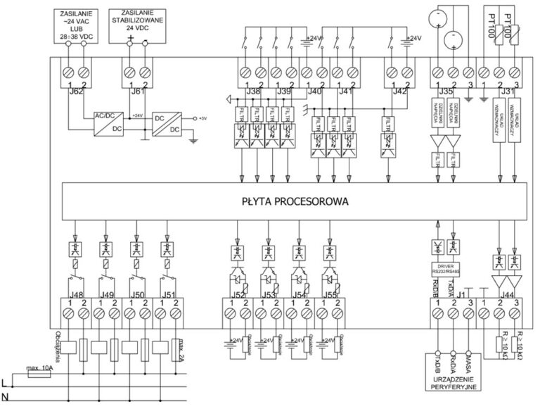
SU 1.2 controller connection diagram
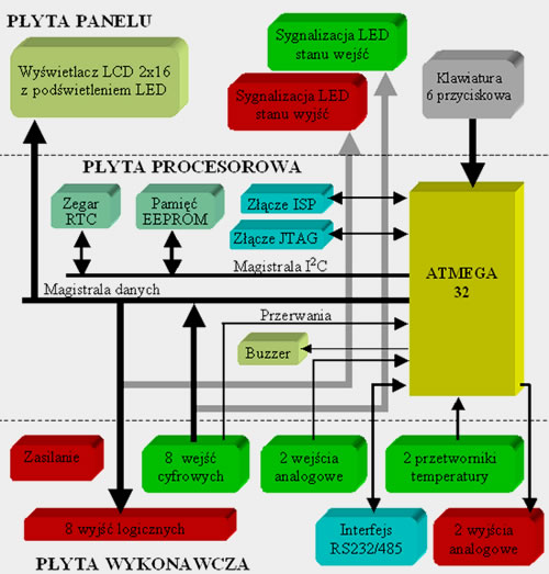
SU 1.2 controller block diagram
Technical parameters
| Blok funkcjonalny | Budowa i opis | Parametry |
| Wyświetlacz LCD | Wyświetlacz sterowany z magistrali danych. Matryca 16×2 (znak x linia) z żółto-zielonym podświetleniem LED. | sterownik zgodny z HD44780 |
| Sygnalizacja LED stanu wyjść | 8 czerwonych diod led SMD, sygnalizujących stan wyjść logicznych. | |
| Sygnalizacja LED stanu wejść | 8 żółtych diod led SMD, sygnalizujących stan wejść cyfrowych. | |
| Klawiatura | Klawiatura 6 przyciskowa podłączona bezpośrednio do mikrokontrolera. | 6 tact switch-y |
| Zegar RTC | Zegar czasu rzeczywistego, w obudowie SMD, który za pomocą na magistrali I2C, jest połączony z mikrokonrolerem. Zegar RTC, z podtrzymaniem akumulatorowym, taktowany jest rezonatorem kwarcowym o częstotliwości 32.768 kHz. | PCF8583, interfejs I2C |
| Pamięć EEPROM | Pamięć EEPROM, w obudowie SMD, która za pomocą magistrali I2C, jest połączona z mikrokontrolerem. | AT24C08, interfejs I2C |
| ATMEGA 32 | Jednostka centralna to mikrokontroler ATmega 32-16A firmy Atmel, w obudowie SMD (TQFP 44), taktowany rezonatorem kwarcowym 14.7456 MHz. | ATmega32-16A, TQFP 44 |
| Buzzer | Elektromagnetyczny sygnalizator akustyczny, z wbudowanym generatorem. | CFG06 |
| Złącze ISP | 10 stykowe złącze ISP do programowania w systemie. | 10-stykowe IDC |
| Złącze JTAG | 10 stykowe złącze JTAG do programowania i testowania w systemie. | 10-stykowe IDC |
| Zasilanie | Sterownik może być zasilany napięciem stałym (stabilizowanym lub niestabilizowanym) lub napięciem zmiennym. | Sposoby zasilania sterownika: – 24V AC, – 24V DC stabilizowane, – 28-38V DC niestabilizowane. |
| 8 wyjść logicznych | Na 8 wyjść logicznych składają się: – 4 wyjścia przekaźnikowe (1 para styków zwiernych beznapięciowych), – 4 wyjścia tranzystorowe. Sterowanie wyjść odbywa się za pomocą magistrali danych. Wszystkie wyjścia logiczne są odizolowane galwanicznie od mikrokontrolera. Natomiast wyjścia tranzystorowe dodatkowo są zabezpieczone przed przepięciami i przeciążeniami. | Przekaźniki: RM40-3021 (8A/250V) Tranzystory: BD437 (0,5A/24V) |
| 8 wejść cyfrowych | 8 wejść cyfrowych (odizolowane galwanicznie od układu mikrokontrolera) odczytywanych za pomocą magistrali danych. Ponadto, 2 wejścia połączone z wejściami przerwań procesora. Na wszystkich wejściach cyfrowych znajdują się dolnoprzepustowe filtry RC. | Nominalne napięcie sygnału wejściowego: +24V |
| 2 wejścia analogowe | 2 wejścia analogowe służą do pomiaru napięcia. Za pomocą zworki, można wybrać zakres napięcia: +5V lub +10V. Rozdzielczość pomiaru ograniczona przetwornikiem A/C mikrokontrolera. | Zakres napięcia wejściowego: +5V lub +10V |
| 2 przetworniki temperatury | 2 oddzielne obwody analogowe służące do pomiaru temperatury za pomocą czujnika PT100. Rozdzielczość pomiaru ograniczona przetwornikiem A/C mikrokontrolera. Każdy obwód wyposażony jest w potencjometr wieloobrotowy, który służy do kalibracji (zrównoważenie zera zależnie od długości przewodu). | Zakres temperatur: -50…+160°C |
| Interfejs RS232/485 | Interfejs szeregowy RS 232/485, odizolowany galwanicznie od układu mikrokontrolera. Za pomocą zworek, można dokonać wyboru pomiędzy interfejsem 232 a 485. | Wyprowadzone linie: RS 232: TxD i RxD RS 485: A i B, prędkość transmisji: do 115.2kbps. |
| 2 wyjścia analogowe | 2 wyjścia analogowe, które za pomocą sterowania PWM, można regulować napięcie. Sterowanie PWM jest odizolowane galwanicznie od układu mikrokontrolera. | Zakres regulowanego napięcia wyjściowego: 0…+10V |

SU 1.2 driver appearance (animation)