
SU 1.5 controller controlling the operation of the cross-flow recuperator
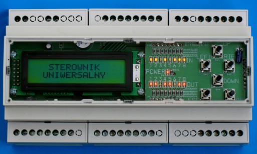
Appearance of the SU 1.5 driver
The SU 1.5 controller controls the operation of the recuperator installed in the ventilation system, which enables heat recovery from the air exhausted from the building. A cross-flow recuperator, which is a heat exchanger, transfers heat through a plate partition, where air flows through channels arranged perpendicular to each other.
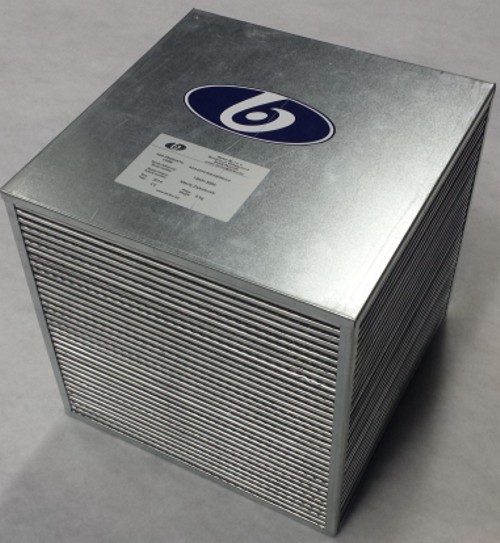
Cross flow recuperator
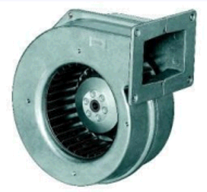
Radial fan
The recuperator is equipped with two EBM PAPST radial fans with electronic commutation, which work as a supply fan and an exhaust fan. These fans are powered by 230 V AC. However, their rotational speed is controlled from the SU 1.5 controller using a 0..10V analog signal. Additionally, the fan speed is read from the fan tacho outputs, which are connected to isolated digital inputs of the SU 1.5 controller, directly supported by interrupts. The rotational speed of both fans is controlled based on parameters read from the AVT flow sensor from HK INSTRUMENTS. The flow is read using analog signals 0..10V. Additionally, the flow sensor has a temperature sensor, the temperature of which is also read by the controller using an analog 0..10V signal.
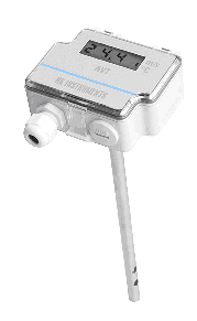
Air flow sensor with temperature sensor
The entire system is equipped with 3 pressure switches. Pressure switch number 1 (heat exchanger) is responsible for opening the damper, i.e. the so-called air recirculation (defrosting). Pressure switches number 2 and 3 are responsible for checking the pressure of the supply filters (filter G4 and F9) and exhaust filters (filter G4). These pressure switches were connected to the isolated digital inputs of the SU 1.5 controller. Additionally, the entire control system can be equipped with additional PT100 sensors, connected directly to the SU 1.5 controller.
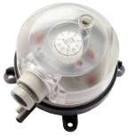
Differential pressure switch
The program was written in C in the Atmel Studio 6.2 environment.
The entire control program was divided into several functional algorithms:
- rotation stability control;
- air flow regulation;
- information display;
- security support;
- function call.
A keyboard is used to change the operating parameters of the recuperator.
The LCD display displays, among others, the following information:
- failure of air supply, exhaust and recirculation;
- recirculation status (enabled or disabled);
- filter condition;
- current fan speed (rpm);
- current air flow (m3/h).
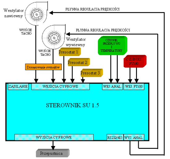
Block diagram of the recuperator control installation